
The Modules of the Vintage ARP 2500 – Part 11
The Modules of the Vintage ARP 2500 – Part 11
If you want to support my work, please make use of the "PayPal" button - thank you very much indeed!
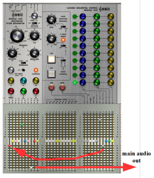
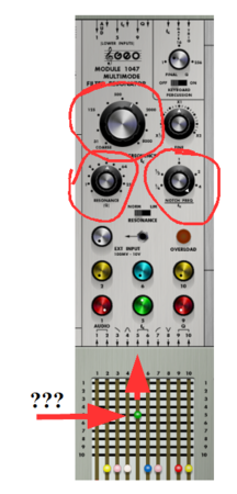
Today´s patch is interesting especially because of the use of the ARP 2500 module “Clocked Sequential Control Module 1027”. when analysing a patch I always ask at first: where does the sound come from in the end, or in other words: What is the last module in the audio chain. Here it is the notch filter output of the Module 1047, the Multimode Filter Resonator of the vintage ARP 2500 from 1970. Well, let´s go further back in the audio chain. The input of the filter module is fed by … wow, by the sequencer! We would have expected, that some oscillator, one of the VCOs of the ARP 2500 would send its sound into the filter. But, no, it is the sequencer.
Alright. It is the clock signal, that is sent to the filter´s audio input. Let´s stay with this clock signal for a moment before we go and look, what the filter is doing with this clock impulse. Let me say it in other words: none of the sequencer´s “regular” CV outputs A, B and C (for pitch modulation or for whatever we want) is used at all. The clock signal comes from the internal clock (which is switched “ON” - see the lit push button) of the sequencer, and is set to LOW range, but at the highest level of the low range. Additionally to this internal settings the clock rate is modulated: the switch in column 6 is set to row 3.
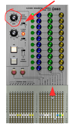
So, where does this modulation come from (remember: this external clock rate CV is added to the
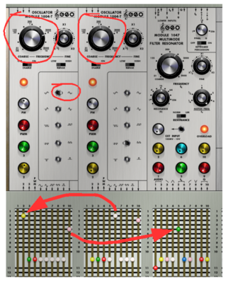
mentioned internal clock rate settings)? OK, this clock rate modulation comes from one of two ARP 2500 Oscillator Modules 1004-T, which is switched to LFO mode (again it is LOW range position). And it is the saw wave of this oscillator, that is added to the internal clock rate of the sequencer. We would expect this rate to linearly increase, and then fall back to these settings again. And indeed, it does.
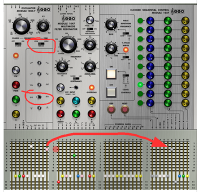
Back to the Filter module. What is happening there? How does the filter deal with the (only) clock rate impulses, which it gets from the sequencer? Well, the centre frequency of the notch filter is set to 1 kHz (big knob), but this centre frequency is modulated by a signal, which arrives through the green switch in column 5 (switched to row 5). The Notch-centre frequency relation is set to maximum, and the resonance is adjusted at a medium high level (please read article 2 concerning the notch-centre frequency relation, if you need to refresh your knowledge about it: https://www.dev.rofilm-media.net/node/351)
And what is the centre frequency modulated by? Well the culprit is the second Oscillator module 1004-T in the patch (the leftmost one). And it is the inverted sine wave of this oscillator, that does the modulation. The oscillator is switched to LFO mode (as is the other of the two VCOs in the patch), and it is adjusted to a higher LFO rate than VCO 1 (the one that modulated the clock rate of the sequencer). Why do I mention this higher rate? Well, because this it is modulated itself! It is modulated by VCO 1, which not only modulates the sequencer´s rate, but also the LFO rate of our VCO 2 here.
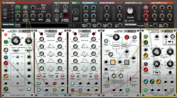
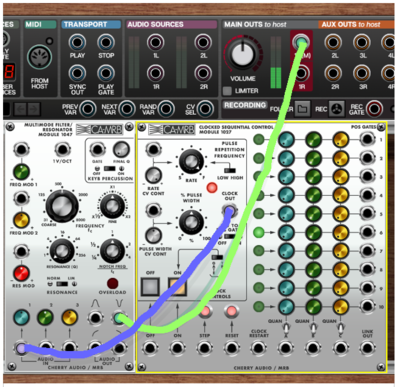
Alright then. Let´s go and transfer that patch to voltage Modular. I´m going to follow the steps mentioned above in my patching now. Therefore I patch the notch filter output of the module 1047 to the main audio out, and the sequencer´s clock out to the filter´s audio in. It doesn´t matter, that the arrangements of the jacks and knobs in Voltage Modular is a bit different from where each front panel element is in the original ARP 2500. I take care, that the adjustments at the sequencer module and at the filter are the same as described above.
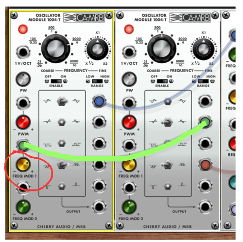
Now I patch a cable from the right VCO (Oscillator Module 1004-T) to the Rate CV input jack. And after adjusting all parameters at the Multimode filter I patch its centre frequency modulation input jack to the output of the left VCO, with all its adjustments set as mentioned above.
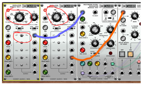
Last thing to do is patching the right VCO´s triangle output to the frequency modulation output of the left VCO. And here we go: we get exactly the same blubs and blips (same rhythm, same sound, same timbres) as with the original.
to be continued.
to part 1: https://www.dev.rofilm-media.net/node/341
to part 2: https://www.dev.rofilm-media.net/node/351
to part 3: https://www.dev.rofilm-media.net/node/356
to part 4: https://www.dev.rofilm-media.net/node/363
to part 5: https://www.dev.rofilm-media.net/node/368
to part 6: https://www.dev.rofilm-media.net/node/377
to part 7: https://www.dev.rofilm-media.net/node/384
to part 8: https://www.dev.rofilm-media.net/node/389
to part 9: https://www.dev.rofilm-media.net/node/397
to part 10: https://www.dev.rofilm-media.net/node/404
to part 12: https://www.dev.rofilm-media.net/node/420
Add new comment