
The Modules of the Vintage ARP 2500 – Part 4
The Modules of the Vintage ARP 2500 – Part 4
(includes embedded video) If you want to support my work, please make use of the "PayPal" button - thank you very much indeed!
Let´s talk about the ARP 2500 module 1036, the sample & hold / Random Voltage module (just by the way: there´s a lengthy video about this module here: https://youtu.be/qzMZeqHhGZQ. Let´s – at least for a moment – recollect what is sampled. This module of the original vintage ARP 2500 synthesizer from 1970 samples levels of the sample source at the time of sampling (some compare it to taking photographs). And “level” means “Voltage”. Sometimes you hear someone telling, that the “dB of the source is sampled at a certain time” - but that´s not the real truth. It´s the Voltage level. Because it is Voltage and its changes, what – for example – oscillator modules generate. Voltage, which is turned to Volume in amplifier circuitry and in speakers etc. a lot later in the signal flow. Each level of voltage corresponds to a certain level of volume, of dB and so on.
It´s not at all frequency or timbre or whatever, what is sampled. Our Sample and Hold units take these levels from the source and hand them over to their outputs, where they stay unchanged until the next sample is taken, the next photograph is shot. Everything that happens to the source between two consecutive samples, two consecutive photographs stays unmentioned at the output of the Sample and Hold module, “gets lost in the Nirwana of modular synthesis.” Wow! How poetical!
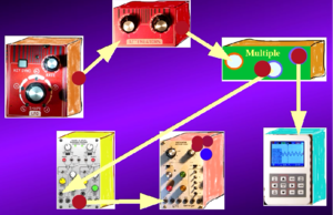
Let me feed the signal from an LFO in the EXT IN jack, where it serves as the source the samples are taken from. But I insert an attenuator in the signal path, and feed the output of the attenuator minto our Sample and Hold module. I modulate the pitch of the oscillator module 1004 with the sample and Hold module´s output. All according to the shown block diagram.
When we watch the voltmeter at the oscilloscope and listen to the pitches the oscillator generates according to the modulating random voltage outputs of the Sample and Hold module while I´m tweaking the attenuator potentiometer, then we see and hear, that by limiting the maximum level of the source I limit the range of the possible pitches – from some octaves to only a few possible pitches with extreme low attenuator adjustments. I´m taming the randomness. This “taming” gets even more obvious, when I use e.g. white noise instead of an LFO as the source the samples are taken from. Just watch the short video demonstrating it all: https://youtu.be/OIfIwurs-ow
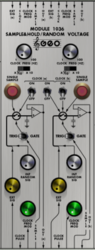
The module 1036 is a double s&H module, and both have a signal input, a signal output and a sample command input. When a pulse is applied to the sample command input the proces of taking a sample from the voltage level at the signal input takes place. I can use the square wave of an LFO, another sample & hold unit´s output (needs an adequate output level), a gate or an trigger signal generator etc. to initiate the sampling. But I can also initiate taking a sample by pushing the red “SAMPLE” button or by using the internal clock generator of the module. By the way: There is long and very detailed video about this module. You get to this video from here: https://www.dev.rofilm-media.net/node/355
There are 2 separate clock pulse generators. The frequencies of the clock pulse generators are determined by the fron panel “Clock Freq” knobs and range switches.An external signal applied to the “Clock Freq Mod” inputs will also affect the clock frequencies. Of the three toggle switches between the above mentioned red sample buttons two are connected to clock A. The switch on the left connects clock A to to Sample & Hold unit A (the left one) while the centre button connects clock A to the Sample # Hold unit B (the right one). The switch on the right connects clock B to the S&H unit B only.
In addition to sampling external signals the module has built-in random signal generators. By advancing the front panel knobs labelled “Int Random Sig” noise can be applied to the signal input of the S&H units. If both is valid: the internal noise generator is switched to the S&H units and an external sample source is fed into the module, then it is the mix of both sources where the samples are taken from.
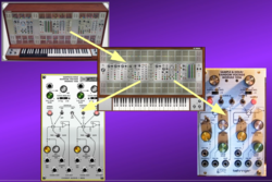
Let´s talk about authenticity of the available remakes (Behringer´s hardware and Voltage Modular´s software – the G2500 is 100% authentical ). Well, there are not a lot differences. Both – the hardware remake as well as the software are nearly 100% authentical (except for the switches of course). Just watch the short video showing and explaining the few differences of Behringer´s ARP 2500 remake and of Cherry Audio´s software version: https://youtu.be/POZwbBkKA0Q
I´m thinking of showing some patch examples in the next article of this series. Well, we will see.
... to be continued
to part 1: https://www.dev.rofilm-media.net/node/341
to part 2: https://www.dev.rofilm-media.net/node/351
to part 3: https://www.dev.rofilm-media.net/node/356
to part 5: https://www.dev.rofilm-media.net/node/368
to part 6: https://www.dev.rofilm-media.net/node/377
to part 7: https://www.dev.rofilm-media.net/node/384
to part 8: https://www.dev.rofilm-media.net/node/389
to part 9: https://www.dev.rofilm-media.net/node/397
to part 10: https://www.dev.rofilm-media.net/node/406
to part 11: https://www.dev.rofilm-media.net/node/413
to part 12: https://www.dev.rofilm-media.net/node/420
Add new comment