
The Modules of the Vintage ARP 2500 – Part 8
The Modules of the Vintage ARP 2500 – Part 8
If you want to support my work, please make use of the "PayPal" button - thank you very much indeed!
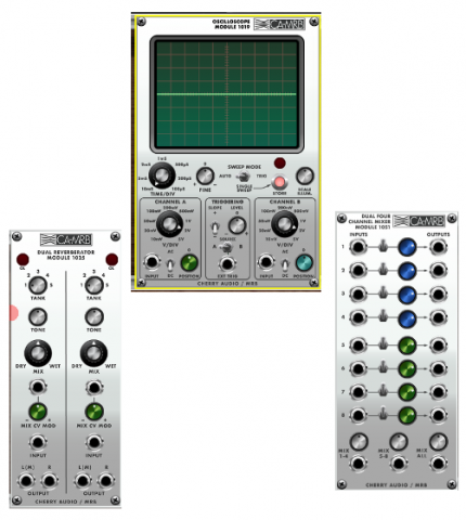
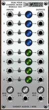
There are 3 modules in Cherry Audio´s software version of the original vintage ARP 2500 modular synthesizer from 1970, which didn´t exist in the real hardware. Cherry Audio has created these added additional modules to enable the user to stick to only the ARP 2500 software package even if there´s the need to comfortably patch something the Eurorack way of patching, which wouldn´t be possible because of the missing switches otherwise (dual 4 channel mixer module 1051).
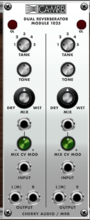
 Another reason for adding is better visibility of what´s really going on in the patch (MRB VM2500 oscilloscope module 1019). And there is a module that ARP had planned to build in their ARP 2500 modular synthesizer series, but never did in the end (dual reverberator module 1025). Let´s have a short look at the details of these modules.
The 1051 Dual Four-Channel Mixer module is a "split" eight-channel mixer for audio or CV signals with a number of unique features. Each of its channels includes a separate out, so it can be used an attenuator or mixer, and in addition to the master 1-8 out, it also includes outputs for channels 1-4 and 5-8 for added flexibility. This module does not actually exist for the original ARP 2500. The original instrument relied on a combination of mixing through its matrix switches and multiple filter inputs.
Inputs, Outputs and ControlsInput Channels
Input jack- Audio or CV input jack.
Enable switch- Turns the input on when in the up position. Down is the same as a typical mixer "mute" button.
Level- This knob adjusts the level at which the input signal is sent to its associated individual output as well as the master outs at the bottom.
Outputs individual out jacks- The output of the signal plugged into the channel only - this allows the switch and knob to be used as a mute and an attenuator respectively.
Outputs
Mix 1-4- The sum of channels 1-4 only.
Mix 5-8- The sum of channels 5-8 only.
Mix All- The sum of all channels.
Now for the reverb:
The 1025 Dual Reverberator contains two independent classic spring-type reverbs. Though ARP planned a spring reverb module, it was never actually produced - this is our take on what it might have been.
Inputs, Outputs, and Controls
Tank- Choose from five different tank choices, each with its own unique tonal and decay characteristics.
Tone- Adds or removes reverb signal brightness by turning left or right from center position.Tone has no effect on dry signals.
Wet/Dry Mix- Balances dry vs. wet signal, with center position corresponding to equal mix.
Mix CV Mod- Allows CV modulation of the Wet/Dry Mix control. The attenuator knob is bipolar; it allow positive (turn right) or inverted voltage control (turn left).
Input jack- Mono audio signal input.
L(M)/R Output jacks- Audio output dry and reverb signal mix. Use the L/M jack for mono applications. The output of the L/M and R jacks are slightly different for effective stereoization of mono signal sources.
Secret "Super Stereo": The two reverb sections are actually slightly different and as a result can be used for a sort of "super stereo" mode. Even though each section has a stereo output, better stereo can be had by separately patching stereo inputs to the left and right sections, selecting identical tanks, and taking the stereo outputs from each L(M) Output jack.
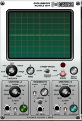 They used to work with these large oscilloscope gadgets (large but for the screen) back in the 1970s. Even I had one to see what my audio signals and control voltages (LFOs, envelopes etc.) looked like. But an oscilloscope module is far more handy of course. The Cherry Audio / MRB VM2500 module 1019 Oscilloscope is a versatile dual-trace scope modelled after analogue units of the 1970s. The 1019 is one of several modules ARP planned to add to the 2500 line, but unfortunately never did. There is no detailed description of what this scope might have been like, so this is Cherry Audio´s take on it, and it's likely far better than what was planned. The 1019 has features found on high-end scopes such as AC/DC coupled inputs, calibrated sweep and vertical amplifiers, single-sweep mode, and variable level triggering from either of the two input channels or an external source.
The Cherry Audio / MRB VM2500 module 1019 Oscilloscope is a versatile dual-trace scope modelled after analogue units of the 1970s. The 1019 is one of several modules ARP planned to add to the 2500 line, but unfortunately never did. There is no detailed description of what this scope might have been like, so this is Cherry Audio´s take on it, and it's likely far better than what was planned. The 1019 has features found on high-end scopes such as AC/DC coupled inputs, calibrated sweep and vertical amplifiers, single-sweep mode, and variable level triggering from either of the two input channels or an external source.
Inputs and Controls
Time/Div- Controls the horizontal sweep speed of the trace. As the knob is turned clockwise, the sweep speed increases and the waveform display spreads out (i.e., zooms). The dial markings, in milliseconds (ms) and microseconds (us), indicate how much time it takes for the sweep to pass one square (division) of the grid. Because it is calibrated, the period and frequency of waveforms can be determined by noting how much time the displayed cycles take.
Example: If the dial is set to 1mS and the waveform takes four divisions to complete a cycle, that means one cycle takes four milliseconds (0.004sec). Using the reciprocal (1/0.004), the frequency of the waveform can be determined: 250Hz. Oscilloscopes can measure frequencies this way when frequency counters have an impossible time with complicated waveforms.
Fine- Provides fine adjustment of the sweep speed. Keep this control at 0 to retain theTime/Div calibration (if you care).
Sweep Mode- Determines how horizontal sweeps are initiated. In Auto mode, the sweep is in "free run" mode, with the next sweep starting immediately after the last one finishes. Single Sweep allows single events to be captured by pressing the Store button. When pressed, one sweep will occur and freeze. The LED illuminates to indicate that this is a stored, frozen waveform. Trig (probably the most frequently used mode) utilizes the Triggering controls in the center and enables stabilization of complex waveforms.
Scale Illum.- Changes the "backlighting" of the grid.
Channel A/Channel B- These are the vertical amplifiers for the two traces. Channel A controls the green trace; Channel B controls the blue trace. Having two different coloured traces is not "70s-correct," but we thought everyone would go crazy deciphering two green traces like an old CRT scope.
V/Div (Volts per Division)- Controls the vertical sensitivity. The dial markings indicate how many volts occupy one vertical square.
Input- Patch input signals here.
AC/DC- In the AC position, this switch allows you to remove any DC offset from the input signal by passing it through a 1Hz highpass filter. The result will always be a vertically centred waveform. In the DC position, the signal passes through unchanged. This control has no effect on the world's most famous mediocre rock band.
Position- Moves the trace up and down. This is very handy for separating the two traces on the screen for easier viewing and comparison. It can also be used to line up features of the wave on the grid for simplified voltage measurements.
Triggering- When Sweep Mode is set to Trig, these controls are used to adjust the sweep triggering to create a stable display. The idea is to start the sweep at the same point in the waveform every time - this way, the waveform doesn't jump all over the place from one sweep to the next.
Slope- Determines which direction the waveform has to be traveling to initiate a trigger (i.e., up or down).
Level- Controls the voltage threshold at which triggering occurs. For example, when viewing a sawtooth wave running through a highly resonant filter (i.e., a very complex waveform), the Level control can be set to trigger at the very top of the highest peak. By picking out this unique feature of the wave, the sweep always triggers at this spot, resulting in a stable display. If Trig mode is currently enabled and no waveform is visible, this means triggering has not occurred - this can be corrected by adjusting the Level control.
Source- Selects triggering from the signal in Channel A or Channel B, or from an external source. Sometimes when looking at complex signals, a simpler signal can be tapped elsewhere in the patch for use as a trigger - this is where Ext Trig comes in handy.
to be continued
to part 1: https://www.dev.rofilm-media.net/node/341
to part 2: https://www.dev.rofilm-media.net/node/351
to part 3: https://www.dev.rofilm-media.net/node/356
to part 4: https://www.dev.rofilm-media.net/node/363
to part 5: https://www.dev.rofilm-media.net/node/368
to part 6: https://www.dev.rofilm-media.net/node/377
to part 7: https://www.dev.rofilm-media.net/node/384
to part 9: https://www.dev.rofilm-media.net/node/397
to part 10: https://www.dev.rofilm-media.net/node/406
to part 11: https://www.dev.rofilm-media.net/node/413
to part 12: https://www.dev.rofilm-media.net/node/420
Add new comment