
The Modules of the Vintage ARP 2500 – Part 7
The Modules of the Vintage ARP 2500 – Part 7
If you want to support my work, please make use of the "PayPal" button - thank you very much indeed!
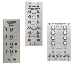
We are approaching the end of this series about the ARP 2500 modules, or better said: we would be approaching the end of the series, if I had not prepared a couple of interesting patches (schematics, explanation and video demonstrations). But let´s learn about the modules 1016 (Noise / Random Voltage), the module 1003 (Dual Envelope Generator) and the module 1033 (Dual Delayed Gate Envelope Generator) first.
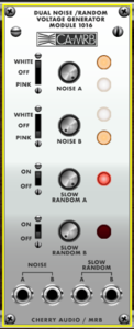
The ARP 2500 synthesizer Module 1016 contains two identical white noise, pink noise and random voltage generators. The two noise outputs (A and B), are generated from two independent diode noise sources, which deliver the white noise. The signal from this raw diode noise generators is sent through a filter to get pink noise and then it is filtered even more to get a succession of slow random voltages. The switches at the left side of the front panel determine, whether the raw white noise or the (filtered) pink noise is sent to the noise outputs A and B. The slow random voltage has got two individual outputs and don´t need to be switched to, but it can be switched on and off (completely and independently from the white/pink noise). There is a middle position of the white-pink noise switches, which switches the noise off completely. The white noise generator produces a flat power bandwidth from 5 Hz to 20 kHz. The pink noise it filtered to attenuate highs and to boost the lower frequencies, which results in an equal energy per octave. The slow random output has peak signal power between 1 Hz and 10 Hz.
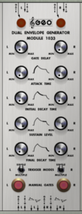
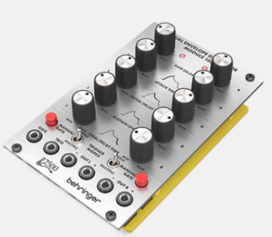
The envelope generator modules 1003 and 1033 of the vintage ARP 2500 modular synthesizer are identical but for the delay functionality of the module 1033, which is missing in the module 1003. In the module 1033 the control signal which starts the envelope always passes through a delay circuit which allows the user to postpone the beginning of an attack from 3 milliseconds up to 3 seconds by adjusting the “GATE DELAY” panel control. That´s the only difference between the module 1003 and the module 1033. Both are dual gate envelope generators. The exponential envelope, which is generated by the modules is a four stage ADSR envelope. Each of the two envelope generators of the modules has also an inverted output.
The operating mode of the envelopes is determined by the switches labelled “TRIGGER MODES”. When this switch is in the position labelled “SINGLE”, the GATE inputs are used to initiate an envelope. The TRIGGER inputs are not used. When the gate signal is applied, the delay circuit is activated. After a time period selected by the front panel “DELAY TIME” control, the delay circuit produces a pulse which initiate the attack. During the attack, the output of the envelope generator rises exponentially up to 10 Volts at a rate determined by the seeting of the “ATTACK TIME” control. When the output of the envelope generator reaches 10 Volts, the attack is ended, and the voltage at the outputs goes through the rest of the envelope´s phases (decay, sustain, release). If the GATE voltage is removed during any part (phase) of the envelope cycle, the output of the envelope generator will always return directly to zero Volts at a rate set by the “FINAL DECAY” time (= release).Similarly, if the GATE voltage is reapplied before the output returns to zero, a new attack will beginn after the time determined by the “TRIGGER DELAY” settings.
When the “TRIGGER MODES” switch is in the “MULTIPLE” position, the attack is initiated by a positive pulse at the “TRIG” input provided that a gate signal is also present. In order to beginn an attack, both the gate and the trigger must be applied. The presence of a gate signal or a trigger pulse alone will not start an attack. A new attack is started every time when a new trigger pulse arrives at the trigger input (as long as a gate signal is present). Even the trigger input is connected to the delay circuit, which then in turn generates the (new) attack.
When the gate signal is applied in the absence of a trigger, the output voltage will rise to the sustain level at a rate determined by the settings of the “INITIAL DECAY TIME” control (whichis NOT identical to the “ATTACK TIME” control !!!). The output voltage level will remain at the sustain level until the gate voltage is removed, at which time the output voltage will return to zero at a time determined by the seetings of the “FINAL DECAY” control. With the original ARP 2500 synthesizer module 1033 (and 1003) there was/is a connection for a sustain pedal on the back panel of the module.
to be continued.
to part 1: https://www.dev.rofilm-media.net/node/341
to part 2: https://www.dev.rofilm-media.net/node/351
to part 3: https://www.dev.rofilm-media.net/node/356
to part 4: https://www.dev.rofilm-media.net/node/363
to part 5: https://www.dev.rofilm-media.net/node/368
to part 6: https://www.dev.rofilm-media.net/node/377
to part 8: https://www.dev.rofilm-media.net/node/389
to part 9: https://www.dev.rofilm-media.net/node/397
to part 10: https://www.dev.rofilm-media.net/node/406
to part 11: https://www.dev.rofilm-media.net/node/413
to part 12: https://www.dev.rofilm-media.net/node/420
Add new comment